|
|
| |
| D.M. Plants |
 |
|
| |
| PROCESS DESCRIPTION |
| There are two basic kinds of demineralizer systems, separate-bed and mixed-bed. In a separate-bed system, cation resins and anion resins and anion resins are loaded into separate pressure vessels. During the service cycle, water passes through the cation bed first, where undesirable positive ions (cations) such as sodium (Na+), calcium (Ca+2), and magnesium (Mg+2) are exchanged for hydrogen (H+) ions. The water next passes through the anion bed, where a similar process removes undesirable negative ions (anions) such as chloride (Cl-), sulfate (SO4-2), and bicarbonate (HCO3-), replacing them with hydroxyl (OH-). Pure water is produced from the combination of hydrogen and hydroxyl ions. In a mixed-bed system, also referred to as a polisher, the cation and anion resins are loaded into the same vessel. |
 |
|
| |
| Where they are in contact with each other. This allows the hydrogen and hydroxyl ions to combine instantaneously to produce water of the highest possible purity. In any demineralizer, the capacity of the resins to exchange ions is finite. As the capacity becomes stressed, ion leakage occurs in the effluent. This is called the breakthrough point. When the breakthrough point is detected, the bed is switched from a service cycle to a regeneration cycle. During the regeneration cycle, the beds are backwashed to flush out particulate matter, then chemically regenerated with acid and caustic. Finally, the beds are rinsed thoroughly to yield a service cycle ready condition.
The breakthrough point of a demineralization bed is impacted by its ion exchange capacity, which is affected by water flow rate, ion contaminant concentration, and feed water composition. Regeneration of a bed is costly, due to the need for chemicals and rinse water, pretreatment, regeneration waste treatment, and labor. Thus the goal is to maintain the service cycle of the bed as long as possible, while ensuring that the system continues to deliver water of the required purity.
Conductivity sensors are successfully employed on demineralizers to monitor the operation of the bed and to predict and signal the all-important breakthrough Point.
In a cation bed, salt impurities are converted to an acid form, typically hydrochloric acid (HCl). When this happens, the conductivity of the water increases dramatically, because the hydrogen ion is far more conductive than the mineral ion it has replace. |
| |
| ION EXCHANGE PROCESS DEMINERARISLISATION |
| INTRODUCTION |
Naturally occurring water in river, wells or lakes, contains impurities both soluble and insoluble. The insoluble or suspended matter can be removed by means of sedimentations and filtration. The sedule impurities mainly consist of alkaline salts such as the bicarbonates and carbonates of Calcium, Magnesium and Sodium and natural salts such as chlorides, soleplates, and nitrates of calcium magnesium, and sodium. In addition to these, silica, carbon dioxide, iron, manganese, organice matter etc. are also found to a lesser degree.
When used in industries for various purposes require purification for removal of the abov impurities can be achieved very easily be demineralization, employing ion exchange resins. |
| |
| ION EXCHANGE PROCESS |
| The dissolved impurities in water in an ionized with calcium, Magnesium, Sodium etc., formatting the captions, chlorides, nitrates etc. formatting the anions.
Ion exchange regions both cation and anion resins are porous materials an inter base to which are attached exchangeable ions. Captions resins have hydrogen and anion resins hydroxyls ions attached to them. When water containing dissolved impurities is passed through a bed of cation resin in Hydrogen from following re-actions take place.
Na Cl + RH = RNa + HCl
Cation resin
Mg(HCO3) + 2RH = R2Mg + 2CO2+ 2H2O
CaSO4 + 2RH = R2Ca + H2SO4
Thus the water emerging from a Cation unit well contain mineral acids corresponding to the mineral salts present in raw water and have low pH.carbonic acid being unstable gets converted into corbon dioxide and water.
When the water from the cation exchanger is failed to anion exchanger containing anion resins in hydroxyl form, the following reactions will take place.
HCl + ROH =RCl + H2O
Anion resin
H2SO4 +2ROH =R2SO4 + 2 H2O
Strong base anion resin can remove carbonic acid (free carbon dioxide and water) also. However, for large plants, if will be economical to remove it by employing a degasser tower packed with a column of rinsing or suitable rings and passing an upward draft of air through the down coming water from cation exchanger.
The ionic load due to cations like calcium, magnesium and sodium are termed as cationic load or total captions and that due to anions like chloride, sulphate, nitrate termed anionic load.
The ionic concentration is normally measured in ppm (milligram per liter) as CaCo3.
Apart form silica and free carbon dioxide, the ions may be present as: Alkaline or neutral salts. The concentration of alkaline salts is determined by measuring the total alkalinity (methyl orange alkalinity) of water. The natural salts content is obtained by measuring the equivalent mineral acidity (EMA which is the sum of the anions chloride, sulphate, nitrate, phosphate).
As the impurities are measured as ppm CaCO3 the total cations should be equal to the total anions ignoring silica and carbon dioxide since water is electrically neutral.
Cationic load = Total Alkalinity + Equivalent Mineral Acidity
Anionic load = Cationicload + Silica + free carbondioxide
IMPORTANT: All the impurities must be expressed in ppm CaCO3 only. The output between regeneration depends upon the type and quantity of resins used, quantity of acid and alkali per regeneration and the dissolved ionic content of the raw water. References is made to the technical data sheet for details. |
| |
| TREATED WATER QUALITY |
| The dematerialized water panty is most conveniently determined by the measurement of its electrical conductivity which is expressed in microchips cm or microsicment cm. The electrical conductivity is affected by ionisable substances such as sodium chloride, sodium hydraoxide, carbonic acid etc. but not by silica.
Demineralisers employing strong base resins product treated water free from carbon dixoide, silica and other dissolved ions. The pH of the water after a cation / Anion Exchanger pair will be around 8.5 to 9.5 units and conductivity in the range 5 to 20 micromhos cm.when the resin gets exhausted, carbondioideand and silica enter the treated water first and if their presence in the treated water is not permissible, the exchangers must be regenerated.
The treated water quality depends upon theeffiency of operation of caption Exchanger. Even 1 ppm of sodium ion escaping from the cation exchanger can increase the treated water conductivity from anion exchanger by about 6 micromhos/cm as the sodium which might escape from cation exchanger will get converted in to a caustic soda in the anion exchanger as per the following equation.
NaCl + ROH = NaOH + RCl. Thus, cation exchanger must be kept in a perfectly regenerated condition. Weak base resin cannot remove carbonic acid but can remove the strong acid like HCl + R (Weak base resin) = RHCl Weak acids, such as silica and carbon dioxide, are thus not removed by the weak base resin. |
| |
| REGENERATION |
| When the ion exchange resins loss all the exchangeable ions, they require regeneration to restore them back to hydrogen or hydroxyl from depending upon when they are cation or anion resins. To active this a 5% to 7.5% concentrated solution Hydrochloride acid is used for cation resin and a 5% to 7.5% concentrated solution caustic soda for anion resin. Sulphuric acid can also be used for Cation Regeneration but the concentration of acid during injection must be such as to prevent calcium sulphate precipitation on the resin. The following reactions take place during regeneration.
Rna + HCl = RH + NaCl
Cation resin
R2Ca + H2SO4 = 2 RH + CaSO4
Strong base
Anion resin< R HCl + NaOH = ROH + NaCl
RHCl + NaOH = R + NaCl+H2O
Weah base Weakly basic
Anionresin
RAW WATER QUALITY: In order to keep the Ion Exchange Resins in a clean state, the inlet raw water the demineralise should be cold, clean and colourless. It is advisable to feed filtered water to the demineralise. The water should be free from chlorine, suspense matter, iron and other heavy metals, organic matter oil algae etc. the impurities irreversibly affect the resin performance and hence should not be permitted to end demineralisation plant. |
| |
| IONIC LOAD & CAPACITY BETWEEN REGENERATION: |
| The output between regeneration from ademineraliser is dependent up on quality of raw water fed into it. The ionic load in water represents the consents of the ions in it. |
| |
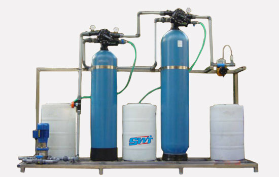
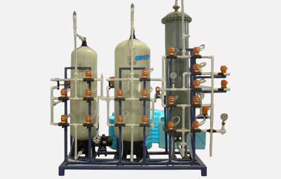
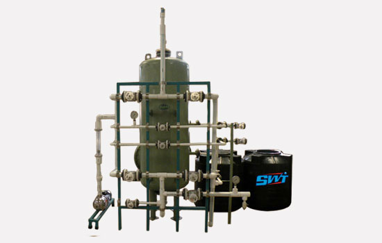
| DESCRIPTION
SWT DEMINERALISER |
| SWT water demineralises come in various capacities. The smaller capacity demineralises are of portable type and there are 4 such models.
The smallest, models are bench models and are decently cabinet made of FRP in which is housed to FRP Cylinder for cation & anion, Access to the inside of the cabinet is form behind where a sliding door is provided. Conductivity cell, meter & circuit box, a multiply valve manifold, are fitted inside the cabinet. The demineralise is operated by controlling then knobs of the value manifold. The conductivity meter indicates the condition of the plant, i.e. Whether the plant is producing demineralised water or it requires regeneration. A PVC regeneration tank is also provided.
Larger unites are of Mild Steel Rubber lined construction. They are provided with distribution & collection systems. For diameters up to 600 mm strainer on plate type system is employed. For diameters up to 600 mm, header-letter type of system is employed. Up flow type of units are offered up to 600 mm diameter. For diameters above 600 mm the down flow type of unites are offered.
The Dermineraliaers employ educators for injecting acid and alkali during regeneration. For cation, FRP tank is supplied and for anion a mild steel tank is provided.
Wastewater from the units are led to sump made of concrete & suiotably lined which acid / alkali proof lining. Orifice board is provided to facilitate measurement of flows during regeneration. |
| |
| INSTALLATION |
SWT For table demineralises are very easy to handle and install. Smaller models sent in knocked down condition in two separate cases. The frost case contains the tubular frame with a Panel Monte on it sent the six- value manifold secured on the panel. Hose connectors are also fixed on the value manifold and hose languets a regenerate tank conductivity cell, conductivity circuit box and motor. The connectors in the FPF cation and anion cylinders are remove prior to dispatch and placed in this case to avoid breakage during transit.
The second case contains only the FRP cation and anion cylinders fitted with trainers and filled what respective resins. The resin are sent in regenerate condition and hence then the plant is assembled and put on to service, one should not demineralised water. However it is advised that regeneration be carried out as per the procedure but lined in this manual. |
| |
| SUPPLY |
| After the packing case have been carefully opened, check that all the aerials are in and that all materials listed in the packing have apperceived.
Remove the packing material on the tubular stand on a level ground near the clime of operation.
Remove the cation and anion cylinders add connect in tube connectors to the caps on the cylinders by screwing the same.
Cation and anion cylinders have the respective labels panted in them. Do not interchange the position of the cylinder on the stand.
Place the casting cylinder on the left side of the stand viewed from the front side and the anion cylinders on the right. Two holds have been provided on the bottom plate of stand and the cylinder necks should sit on them. Place the PVC coated plate (Supplied loose) on the stop the 2 cylinders well secured and would not fall off the stand. That the cylinders are in a vertical position. Make the hose connection as given in the enclosed sketch.
Place the regenerate cylinder on of the panel and screw the connectors to the bottom of the tank. Remove the 8 nuts on the connects enter and fixed the conductivity circuit box on the rear side of the frame (holes are provided) using the brass screws supplied. Fix the conductivity cell also on the frame in similar manner. On the circuit box, 3 wires come out from the circuit. two are> core and the other 2 core wires. The 3 cur wore should be connect to a 220 v power supply. The cable coming from the second hole on the circuit is marked CELL¬ and should be connected to the two terminals on the cell. The third wire should be connected to the positive terminal on the meter and black wire to the negative terminal. If the rivers are done, irreparable demand will occur to the meter. Once the above are done, the demineralise is ready for operation. |
|
|
|